SVGMarks can be used to process images for electron-beam lithography or for general purposes.
General purpose
This part of the manual demonstrates the use of SVGMarks when processing general purpose images, e.g., how to remove distortions in an image taken by a smartphone. You can also watch the corresponding video tutorial.
Click one of the buttons below to jump to the appropriate section of the manual related to general purpose image processing.
General purpose SettingsGeneral purpose image processing
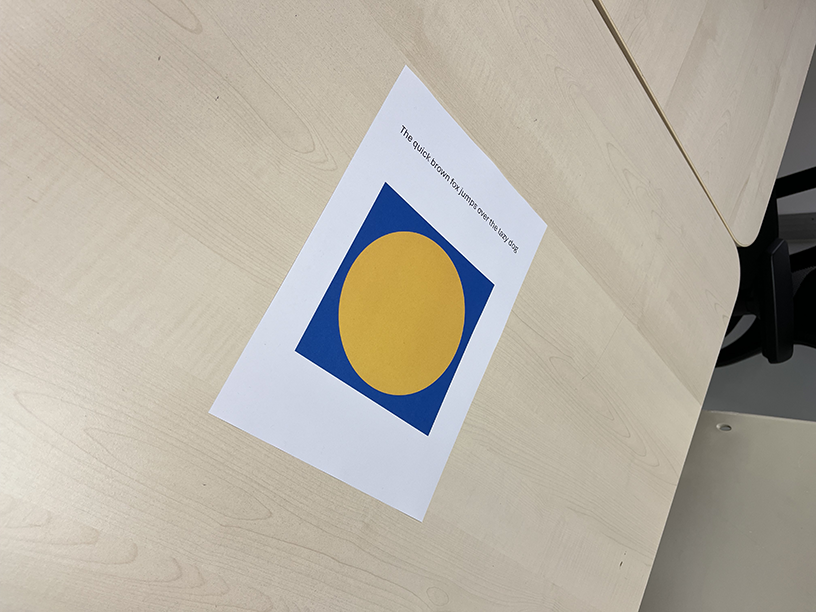
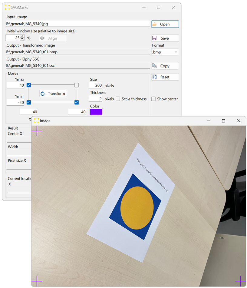
General purpose images, such as those taken with a smartphone, usually have a large perspective distortion. Perspective distortion can only be removed with 4 marks. Figure 1 shows such an image containing an A4 paper with some text and two geometric objects. Due to the perspective of the image, the exact nature of the geometric objects is not clear, e.g., the white A4 paper looks more like a irregular quadrilateral than a rectangle. In this example, four marks are used to remove the perspective distortion and display the image as if it were viewed directly from above.
To remove the distortion in the image, follow the steps below:.
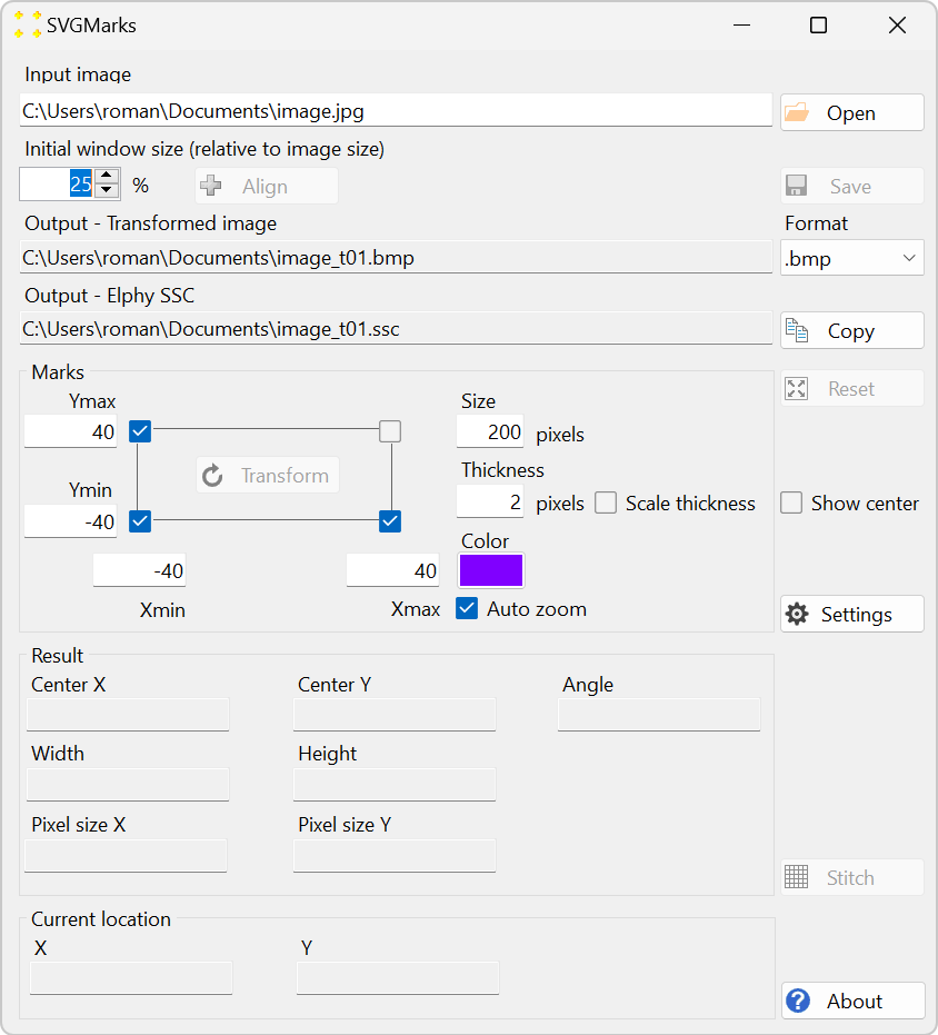
This step is optional. Use the "Initial window size (relative to image size)" numeric box (see Figure 2) to reduce the image size to 25% before opening the image. This will make the image more manageable by reducing the on-screen image size from the original 4032 pixels x 3024 pixels (in this particular case) to a more comfortable 1008 pixels x 756 pixels. It is also advisable to increase the size of the marks, e.g., 200 pixels is used in this example.
Click the "Open" button to open and browse for the image. This will open the image after it is selected, as shown in Figure 3. Figure 3.
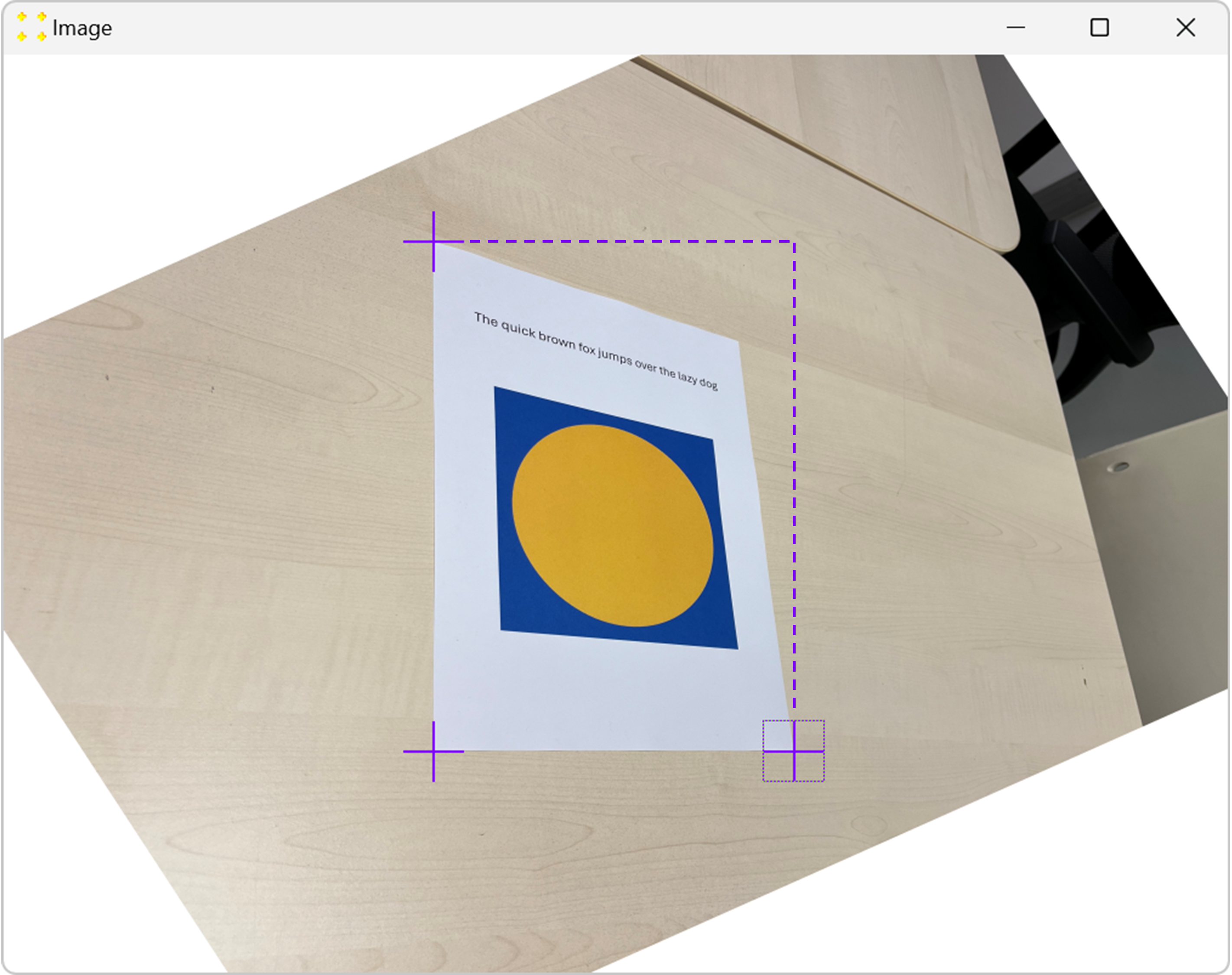
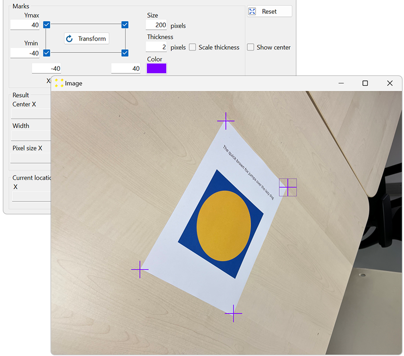
Select the check box corresponding to the fourth mark in the upper right corner to display that mark in the image. Use the mouse to place the marks roughly over the corners of the A4 paper, as shown in Figure 4. To move the mark, click anywhere within the square that defines the mark, then drag the mark to the desired location.
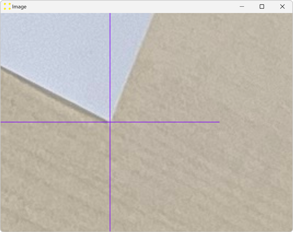
To fine-tune the position of a mark, double-click anywhere within the square that defines the mark. This will zoom in on the mark, as shown in Figure 5. In the zoomed image, use the mouse again to fine tune the mark so that its center coincides with the corner of the A4 paper. When the fine adjustment is complete, double-click inside the mark again to zoom out. This procedure should be repeated for all marks.
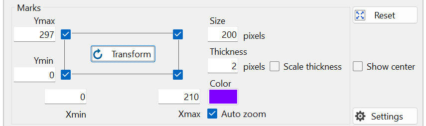
Enter the size of A4 paper in the corresponding text boxes "Xmin", "Xmax", "Ymin", and "Ymax" next to the check boxes. In this case, enter Xmin = 0, Ymin = 0 (mark in the bottom left corner), Xmax = 210 (mark in the bottom right corner), and Ymax = 297 (mark in the top left corner). This is shown in Figure 6. Alternatively, the aspect ratio of the object can be used, e.g., 210 can be replaced by 1 and 297 by 1.4143 = 297/210 (which is the square root of 2).
Click the "Transform" button shown in Figure 6. The transformed image is immediately displayed in the image window shown in Figure 7. The A4 paper now looks as if it is being viewed directly from above, without any perspective distortion.
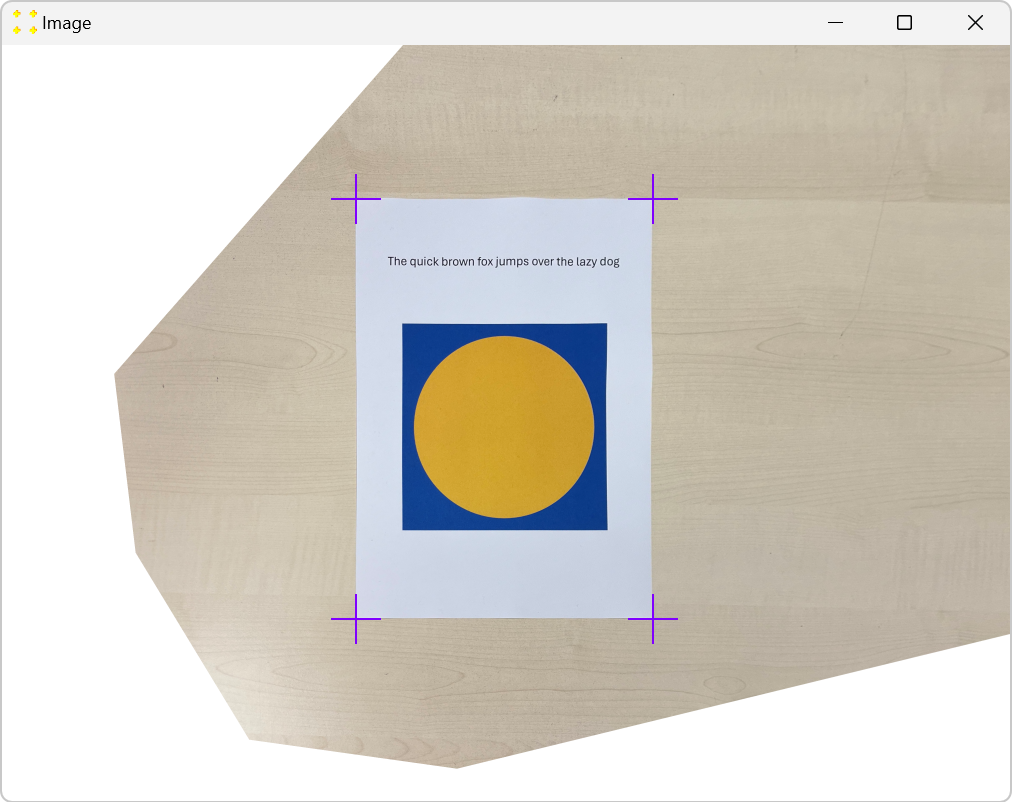
Figure 7. Image after perspective distortion correction. By default, the transformed image is saved in BMP format in the folder of the original file, as shown in Figure 8. The format of the image can be changed before the image transformation by selecting the desired format in the "Format" combo box. However, if the image is transformed to be placed in Raith Nanosuite, the default BMP format should be used, as the Raith software does not support other image formats.
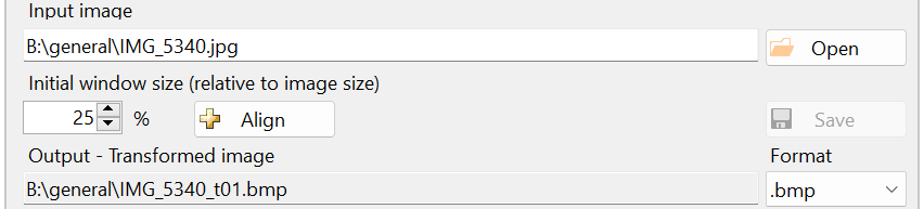
Figure 8. The output image is saved in the same folder as the input image.
Note that all 4 marks must be used to remove the perspective distortion. Figure 9 shows the result of the transformation using only 3 marks (without using the mark in the top right corner). Although the aspect ratio and the straight angle are restored between the 3 corners of the A4 paper, the fourth (top right) corner is in the wrong position if the top right mark is not used. This is because the rotation and shear transformations are not sufficient to correct the perspective distortion.