This part of the manual demonstrates the use of SVGMarks when processing images for electron-beam lithography. You can also watch the corresponding video tutorials. The files used in this manual can be downloaded from the Download section as a single zip file containing the used images and the design file in GDSII format.
After image transformation, the image can be automatically placed in a design file opened in Raith Nanosuite. The image can also be placed in other nanofabrication CAD software by manually inserting the coordinates provided by SVGMarks. If your nanofabrication software is not supported, please contact the author.
Click on one of the buttons below to jump to the appropriate section of the manual related to image transformation in electron-beam lithography.
Transformation of a single image (see also the video tutorial)
SVGMarks can be found in the Start menu after installation, as shown in Figure 1.
Figure 1. SVGMarks in the Windows 11 Start menu.
Run SVGMarks. The window shown in Figure 2 will appear.
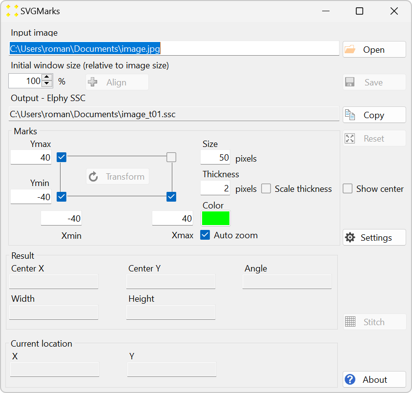
Figure 2. The main window of SVGMarks. The text box at the top ("Input image") contains the file name of the image to be processed. Initially, the program offers image.jpg stored in your personal folder (as an example - this image probably does not exist on your PC). The text box "Output - Elphy SSC" contains the name of the output SSC file, which will be created by SVGMarks during processing in the same folder (its name is derived from the file name of the input image).
Click the "Open" button to open the image you want to transform. If you prefer, you can type the full file name in the text box instead of browsing for the image. If you choose to type, press the Enter key when you are finished to tell the program that your input is finished and that you want to open the image. The selected image will instantly open in a separate window, as shown in Figure 3.
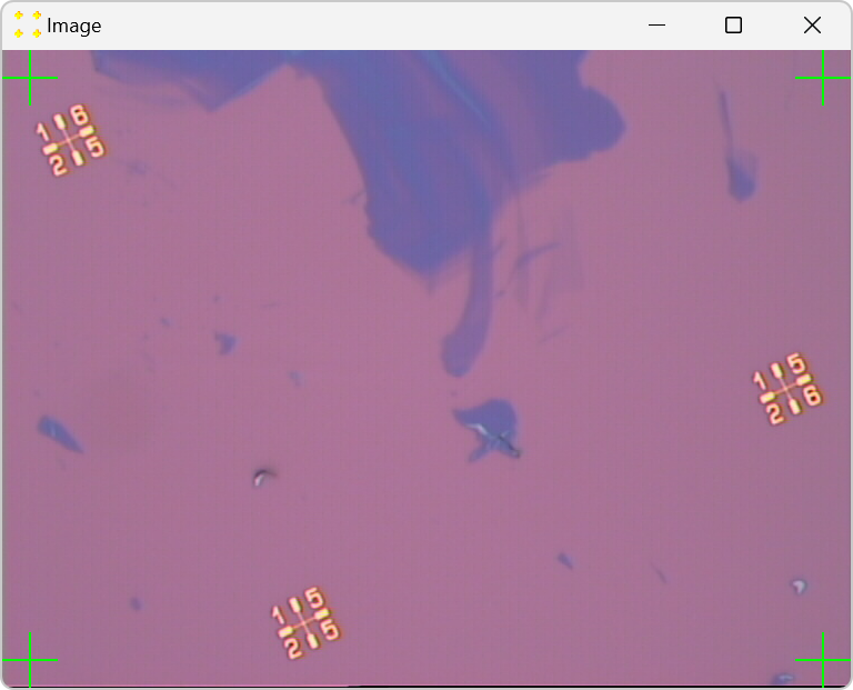
Figure 3. Opened optical image with transformation marks (green marks are used in this example; the color can be changed, as discussed below) placed by SVGMarks. The image shows graphene flakes of different thicknesses (from a monolayer to a thick multilayer). Three gold marks (in yellow), patterned by electron-beam lithography, are also visible. They define the local coordinate system of the image. In this image, the sample is deliberately rotated counter-clockwise by about 26 degrees to demonstrate the capabilities of SVGMarks. In reality, the axes of the local coordinate system should be as parallel as possible to the edges of the image (i.e., the line connecting the two lowest patterned marks should be as parallel as possible to the horizontal edge of the image).
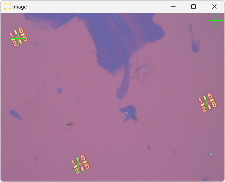
Use the mouse to place the green marks roughly over the corresponding gold marks in the image, as shown in Figure 4. To move the green mark, click anywhere within the square that defines the green mark, then drag the green mark to the desired location. In most cases, the best image correction is achieved with three green marks, in which case SVGMarks applies both rotation and shear transformations to the image. The unused fourth green mark is ignored (the check boxes are used to tell the program which marks to use, as discussed below). If there are only two patterned gold marks in the image, please use only two corresponding green marks (in this case SVGMarks will only rotate the image).
In the case of highly distorted images, the fourth mark should be used, in which case SVGMarks applies an additional perspective transformation. In this example, the fourth green mark cannot be used because the fourth gold mark is not visible in the image due to excessive image rotation. The four-mark transformation is demonstrated in the General purpose section of the manual.
Figure 4. Three green marks are placed over the gold marks in the image.
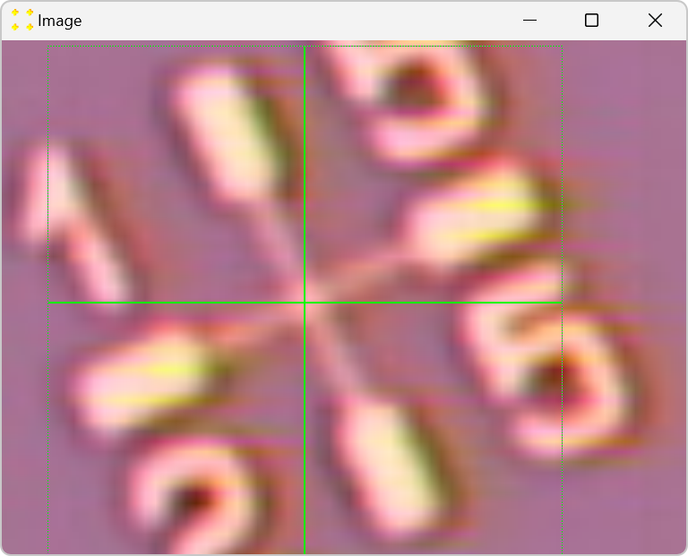
To fine-tune the position of a green mark, double-click anywhere within the square that defines the green mark. This will zoom in on the green mark, as shown in Figure 5. Alternatively, click once on the green mark to select it and then press key 3 (or 4) to zoom in on the mark (this shortcut is implemented for users of the previous version SVGMarks 3.x, which used Inkscape for mark positioning). In the zoomed image, use the mouse again to fine tune the green mark so that its center coincides with the center of the patterned gold mark. When the fine adjustment is complete, double-click inside the green mark again to zoom out. Alternatively, click once on the green mark to select it and then press key 3 (or 4) to zoom out. This procedure should be repeated for all marks.
Figure 5. The selected green mark (the one in the bottom left corner) is zoomed in and placed over the gold mark in the image.
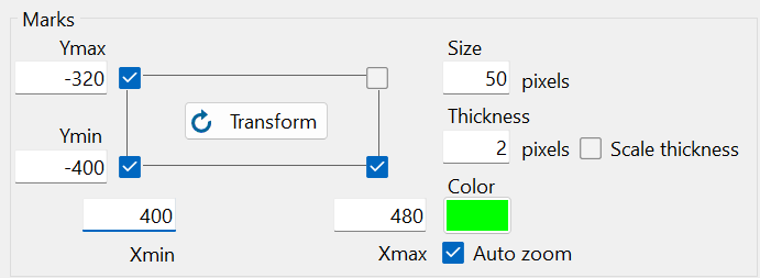
Use the check boxes shown in Figure 6 to select which green marks should be used to transform the image. In the previous example, three marks were used (in the bottom left, bottom right, and top left corner) and their check boxes should be checked. Type the coordinates of the marks in the corresponding text boxes "Xmin", "Xmax", "Ymin", and "Ymax" next to the check boxes. Values and units should correspond to the design file. In this case, Xmax = 1920 and Ymax = 1080.
Figure 6. The selection of check boxes and coordinates that correspond to this example.
Click the "Transform" button shown in Figure 6. The transformed image is immediately displayed in the image window shown in Figure 7.
Figure 7. After the transformation, the transformed image is displayed in the same image window in which the original image was opened (see Figure 3).
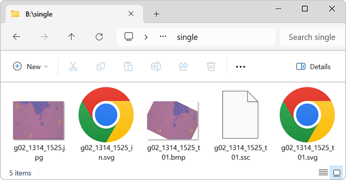
The transformed image is saved in BMP format in the folder of the original file, as shown in Figure 8. Although a different image format can be selected in the "Format" check box, use only the BMP format for Raith Nanosuite, which cannot handle other image formats. Besides the transformed image, the program also creates two auxiliary SVG files and one SSC file. The latter file is used to place the transformed image in the design file opened in Raith Nanosuite.
Figure 8. All files are saved in the same folder as the original image. In addition to the input image and the output SSC file, SVGMarks also creates the transformed image in BMP format (this image will be displayed in the design file) and two auxiliary files in SVG format.
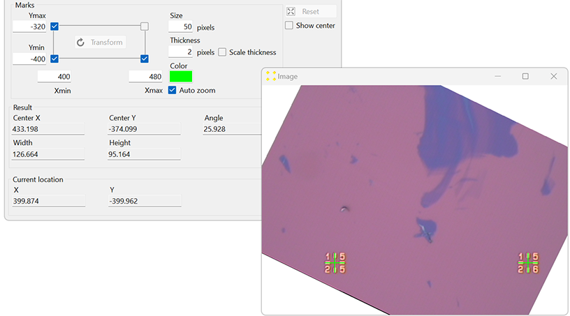
The coordinates of the image center and the image dimensions are displayed in the Result group at the bottom of the main SVGMarks window, as shown in Figure 9. These data can be used to correctly place the image in the design file other than Raith Nanosuite. After the transformation, the program knows the coordinate system of the transformed image. Consequently, hovering the mouse over the transformed image will display the mouse coordinates in the Current location group at the bottom of the main SVGMarks window.
Figure 9. The "Result" group shows the coordinates of the center of the transformed image, the angle by which the original image was rotated (provided only as a reference because the transformed image will be used in the design), the width and height of the transformed image, and the pixel size in both directions. The "Current location" group shows the coordinates of the mouse when it hovers over the transformed image. In this example, the mouse hovers over the mark in the bottom left corner.
The transformed image is ready to be imported into the design file because both files have the same coordinate systems. The following part of the manual explains how to place the transformed image into the Raith Nanosuite design file (keep SVGMarks open).
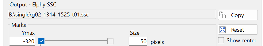
Click the "Copy" button to copy the file name of the SSC file, see Figure 10. SVGMarks can now be closed if it is not needed.
Figure 10. The "Copy" button is used to copy the file name of the SSC file to the Windows clipboard.
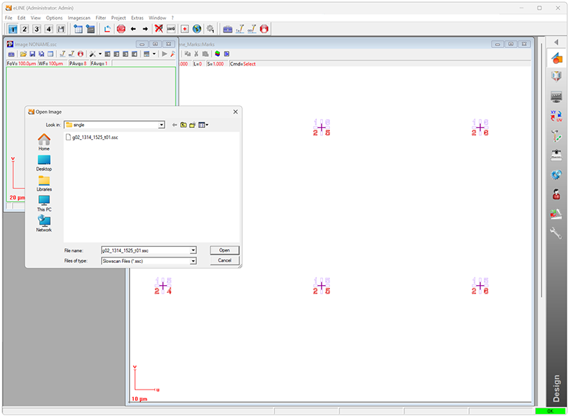
Open the design file in Raith Nanosuite. The design file corresponding to the image in this example is shown in Figure 11. To open the transformed image, click on "File" → "Open image..." and paste the file name you copied above (see Figure 10) into the "File name" text box of the "Open Image" dialog. Click "Open" to open the transformed image.
Figure 11. Raith Nanosuite with the open design file (large white window on the right). To open the transformed image, paste the SSC file name into the "File name" text box of the "Open Image" dialog.
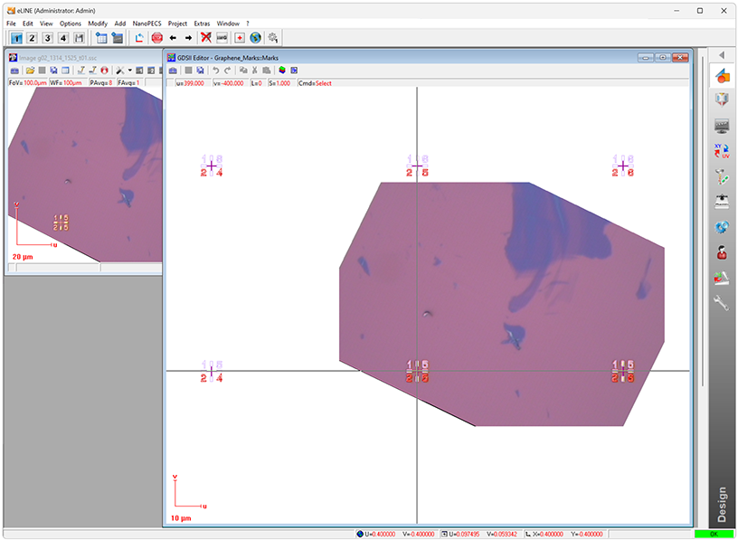
To show the transformed image in the design file, click on the design file window to bring it to the foreground, and then click "Options" → "Show Video". The transformed image will appear in the design file, as shown in Figure 12.
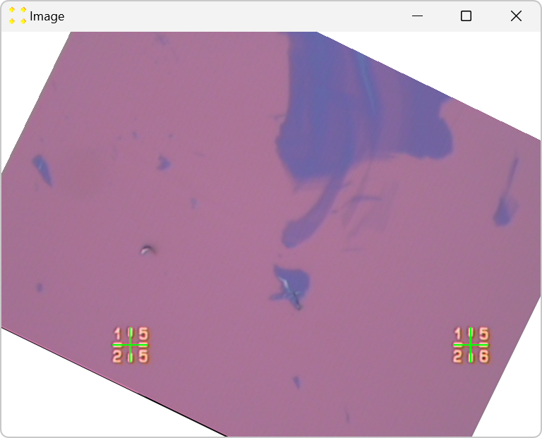
Figure 12. Transformed image placed at its position in the design file.
The fine alignment of the transformed image can be seen by zooming in on the visible marks, as shown in Figure 13.
Figure 13. Enlarged portions of the design file around marks showing the fine alignment of the transformed image with respect to the design file.
The following list explains the controls and actions in the main SVGMarks window that were not used in the above manual.
If you are not satisfied with the transformation, you can return to the original (untransformed) image by clicking the 'Align' button.
When you click the "Transform button", the position of the marks in the original (untransformed) image is automatically saved before the transformation is performed and the transformed image is opened. If you want to save the position of the marks in the untransformed image for a later session (without transforming the image), click the "Save" button.
If you want to open an image that has previously been transformed, click the "Open" button and open the original (untransformed) image. Once the image is open, SVGMarks will set the mark location in the image (Figure 4) and the transformation parameters (Figure 6) as they were set the last time the image was transformed. If you would like to see the transformed image, click the button "Transform".
By default, SVGMarks opens images in their original resolution. This can be a problem if, for example, the image was taken at a higher resolution than that of the screen. In this case, the image window will be larger than the desktop. Although a user can resize the image window, it is more convenient to tell SVGMarks to open the resized image window from the start. Use the numeric field "Initial window size (relative to image size)" to set the ratio between the resolution of the image window and the image. For example, if this numeric field is set to 50 % before opening an image, the displayed image will have half the resolution of the original image (it will be twice as small as the original image).
The position of the marks in the image window can be reset by clicking the "Reset" button.
To manually zoom in/out, scroll the mouse wheel. In this case, the image is zoomed in/out relative to the center of the image window. Double-click on any feature in the image to move it to the center of the image window. If the feature is within the square defined by a mark, uncheck the "Auto zoom" check box to avoid zooming in/out on the mark.
If you double-click outside the square defined by a mark during mark positioning (Figure 4 and Figure 5), the image will be centered at the point where you double-clicked (i.e., the image will be moved within the image window instead of zoomed to a mark). The position of the image within the image window has no effect on the image transformation. However, if you prefer to return the image in the center of the image window, you can:
double-click on the mark (to zoom in) and then double-click again to zoom out (this is the quickest way to re-center the image as the images are always centered when you zoom out) or
double-click on the actual center of the image (which is not always easy to find) or
click the "Reset" button (this will also reset the position of the marks, which is the main purpose of this button).
The numeric fields "Size" and "Thickness" set the dimensions of the marks in the image window (in pixels). The "Color" button sets the color of the marks in the image window. Changing any of these settings will immediately change the appearance of the marks in the image window.
When an image is opened for the first time, the thickness of the marks is set using the 'Thickness' numeric field. In the example above, the mark thickness was set to 2 pixels. Double-clicking on a mark will zoom the image to the mark by an appropriate factor (Figure 5). If the 'Scale thickness' check box is unchecked, as in the example above, the thickness of the zoomed mark will not change (it will remain 2 pixels in the example above). However, if this check box is checked, the thickness of the zoomed mark will be increased by the same zoom factor.
Check the "Show center" check box to display the center of the image window.