SVGMarks can be used to process images for electron-beam lithography or for general purposes.
Stitching in electron-beam lithography
This part of the manual demonstrates the use of SVGMarks when processing multiple images taken by an optical microscope or SEM. You can also watch the corresponding video tutorials. The files used in this manual can be downloaded from the Download section as a single zip file containing the used images.
After image transformation and stitching, the image can be automatically placed in a design file opened in Raith Nanosuite. The image can also be placed in other nanofabrication CAD software by manually inserting the coordinates provided by SVGMarks. If your nanofabrication software is not supported, please contact the author.
Click one of the buttons below to jump to the appropriate section of the manual related to image stitching.
Untransformed images Transformed imagesStitching untransformed images (see also the video tutorial)
Microscopes equipped with a motorized stage can be programmed to capture multiple images of a sample. Using the stitch option, SVGMarks can seamlessly merge smaller images into a single, high-resolution image of the sample. This technique is particularly useful when the microscope cannot directly capture a large image at the same high resolution as the smaller ones.
The images can be stitched either with or without prior transformation (the process of transformation is explained in detail in Transformation). This part of the manual focuses on the more common case of stitching untransformed images, as stitching transformed images requires marks fabricated on the sample. For more details on stitching transformed images, see Transformed Images.
Figure 1 displays the contents of a folder containing 24 images captured using an optical microscope with a motorized stage (Leica DM6 M).
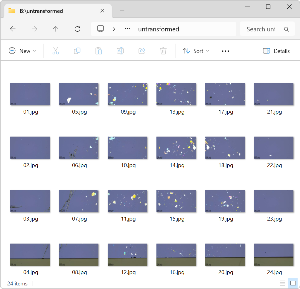
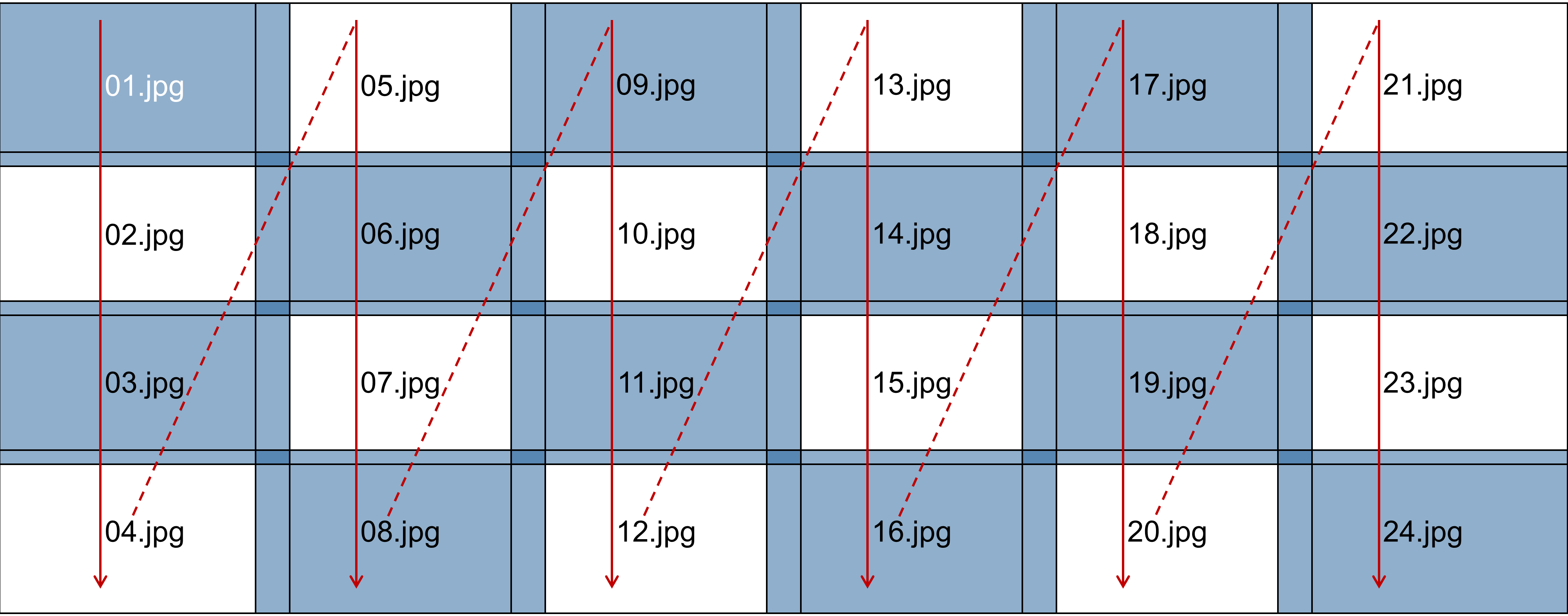
Figure 2 illustrates the raster scan pattern used by the microscope to capture the images. Starting at the top-left corner, the microscope captured images sequentially down the leftmost column, labeled "01.jpg", "02.jpg", "03.jpg", and "04.jpg". It then moved to the top of the next column to capture the next set of images ("05.jpg", "06.jpg", "07.jpg", and "08.jpg"). This process continued column by column until all 24 images across the 6 columns were captured.
To stitch all images, perform the following steps:
-
Open one of the images in SVGMarks. The choice of the initial image is arbitrary, but for simplicity, it is recommended to start with the first image captured by the microscope, which in this case is "01.jpg." This image will be referred to as the reference image.
Before opening the reference image, it is advisable to set the "Initial window size" to 60% (to reduce the size of the image windows in SVGMarks, as the images are captured at a resolution of 1920×1080) and to set the file "Format" to ".jpg" (to minimize the size of the generated files). Figure 3 shows the settings and the opened image "01.jpg".
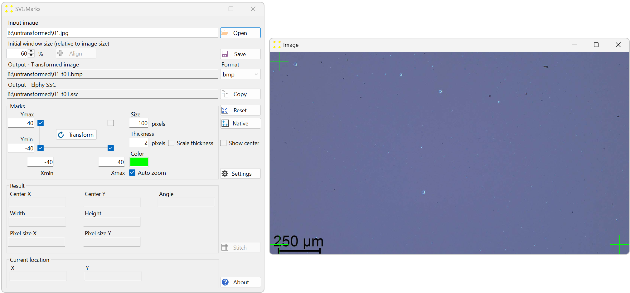
Figure 3. The reference image opened for stitching. The settings are as follows: the "Initial window size (relative to image size)" numeric box is set to 60%, the "Format" combo box is set to ".jpg", and the "Size" text box (mark size) is set to 100 pixels. -
Click the "Native" button to perform the native transformation of the image. This will automatically position the three default marks at the exact corners of the image, as shown in Figure 4. Their coordinates are set to match the image size in pixels. In this case, the coordinates are Xmax = 1920 and Ymax = 1080. The automatic native transformation is necessary to define the image size, which is essential for stitching all captured images into a single mosaic image.
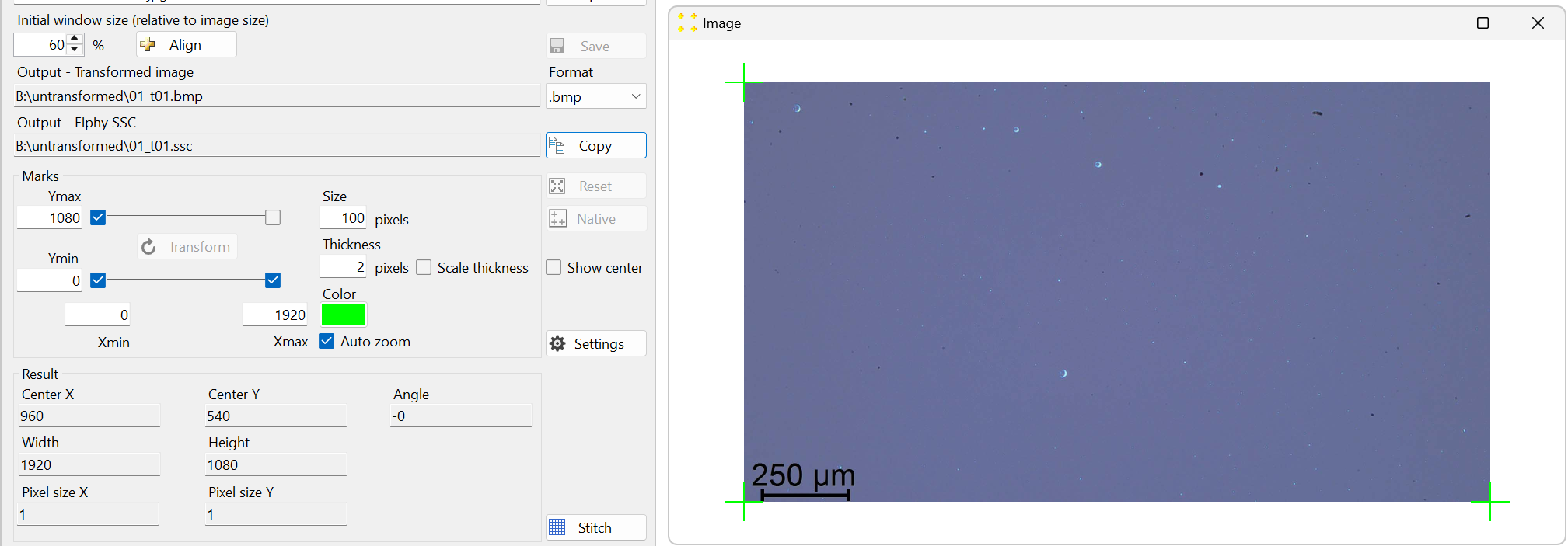
Figure 4. The result of the native transformation of the image "01.tif." The image is zoomed out (using the mouse scroll wheel) to reveal the three default marks positioned at the exact corners of the image. -
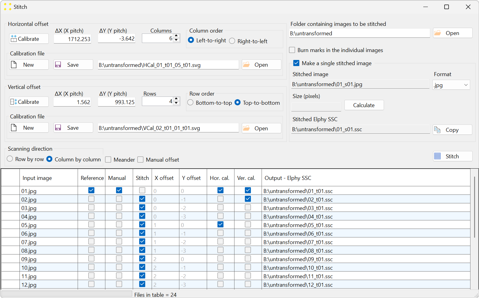
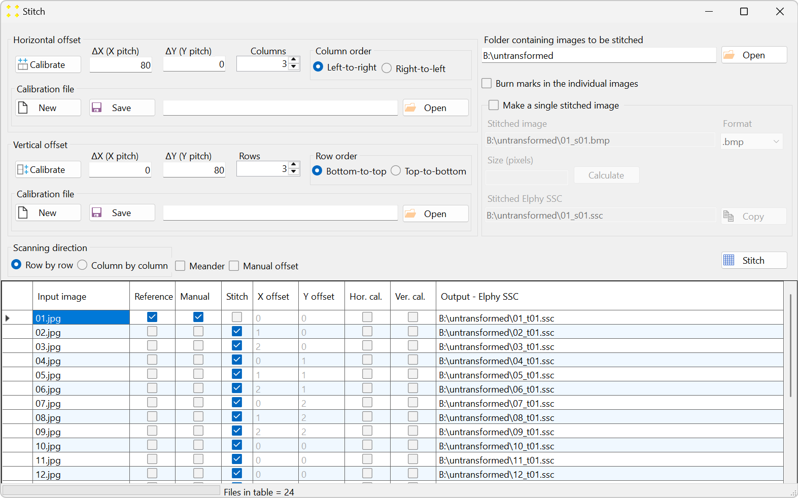
Click the "Stitch" button to open the "Stitch" window, as shown in Figure 5. All 24 images are listed in the table in alphabetical order, which is the typical naming convention for images captured by a microscope. The settings in the "Stitch" window should be configured so that the alphabetical order in the table aligns with the scanning pattern used to capture the images, as illustrated in Figure 2.
Set the stitch parameters as follows (the numbering corresponds to that of Figure 6):
- The number of columns is set to 6.
- The columns are scanned from left to right.
- The number of rows is set to 4.
- The rows are scanned from top to bottom.
- The scanning direction is column-by-column.
- Check the "Make a single stitched image" checkbox to create the mosaic image.
- Select the ".jpg" file format in the "Format" combo box to reduce the size of the mosaic image (optional).
The settings above configure the scanning direction but do not specify the distance (i.e., offset) between the images in the horizontal (x) and vertical (y) directions. To set the distance between the images, two neighboring images in both the horizontal and vertical directions should be selected. The choice of images is arbitrary; it is only important that the neighboring images (which overlap) are selected. For example:
- The images "01.jpg" and "05.jpg" are selected as two neighboring images in the horizontal direction (see Figure 2). The selection is made in the "Hor. cal." column of the table shown in Figure 5.
- The images "01.jpg" and "02.jpg" are selected as two neighboring images in the vertical direction (see Figure 2). The selection is made in the "Ver. cal." column of the table shown in Figure 5
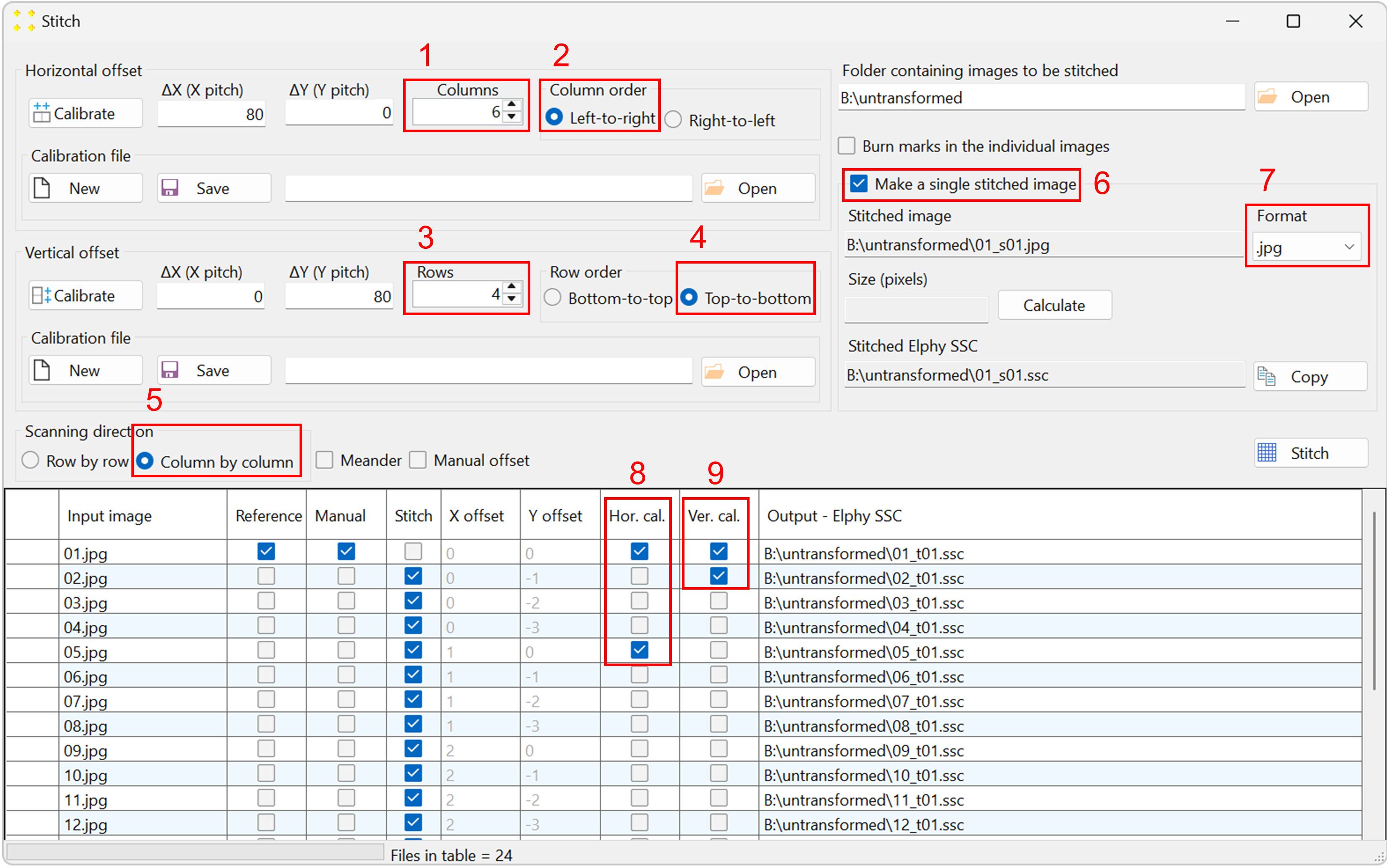
Figure 6. The correct settings in the "Stitch" window, which correspond to the raster scan shown in Figure 2. -
Click the "Calibrate" button in the "Horizontal offset" group box to open the images used to determine the horizontal offset between neighboring images. This will display images "01.jpg" and "05.jpg" side by side, each with a single mark at its center, as shown in Figure 7. The images are separated by a line of the same color and thickness as the marks. The image "05.jpg" is displayed to the right of the image "01.jpg", which corresponds to the selected settings in the "Stitch" window (based on Figure 2).
Roughly align the marks with the common feature visible in their respective images, as shown in Figure 8.
Double-click the marks to zoom in and precisely align them with the common feature, as shown in Figure 9. The zoom-in procedure is explained in detail in Single image.
Close the window with the images and save your changes.
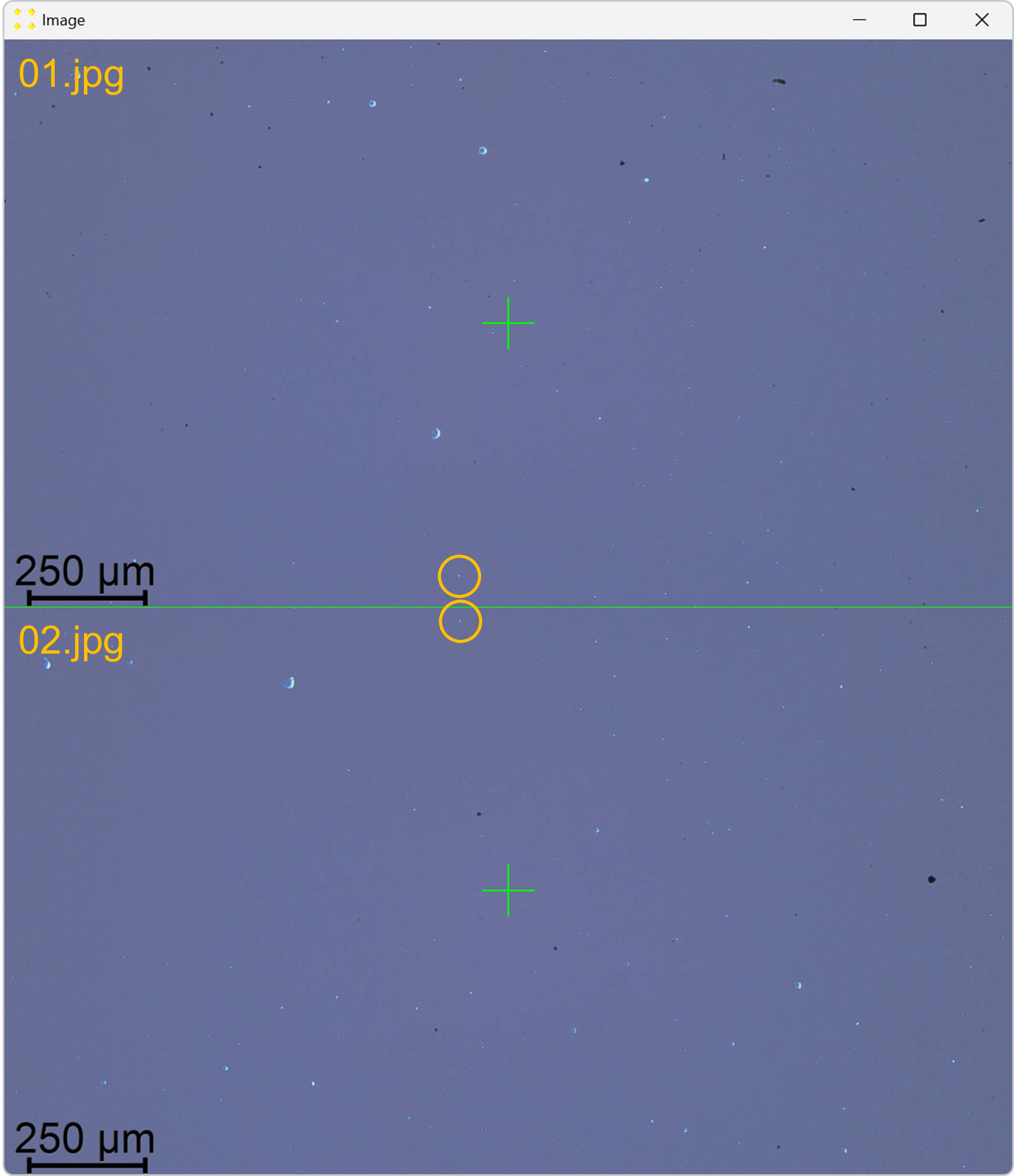
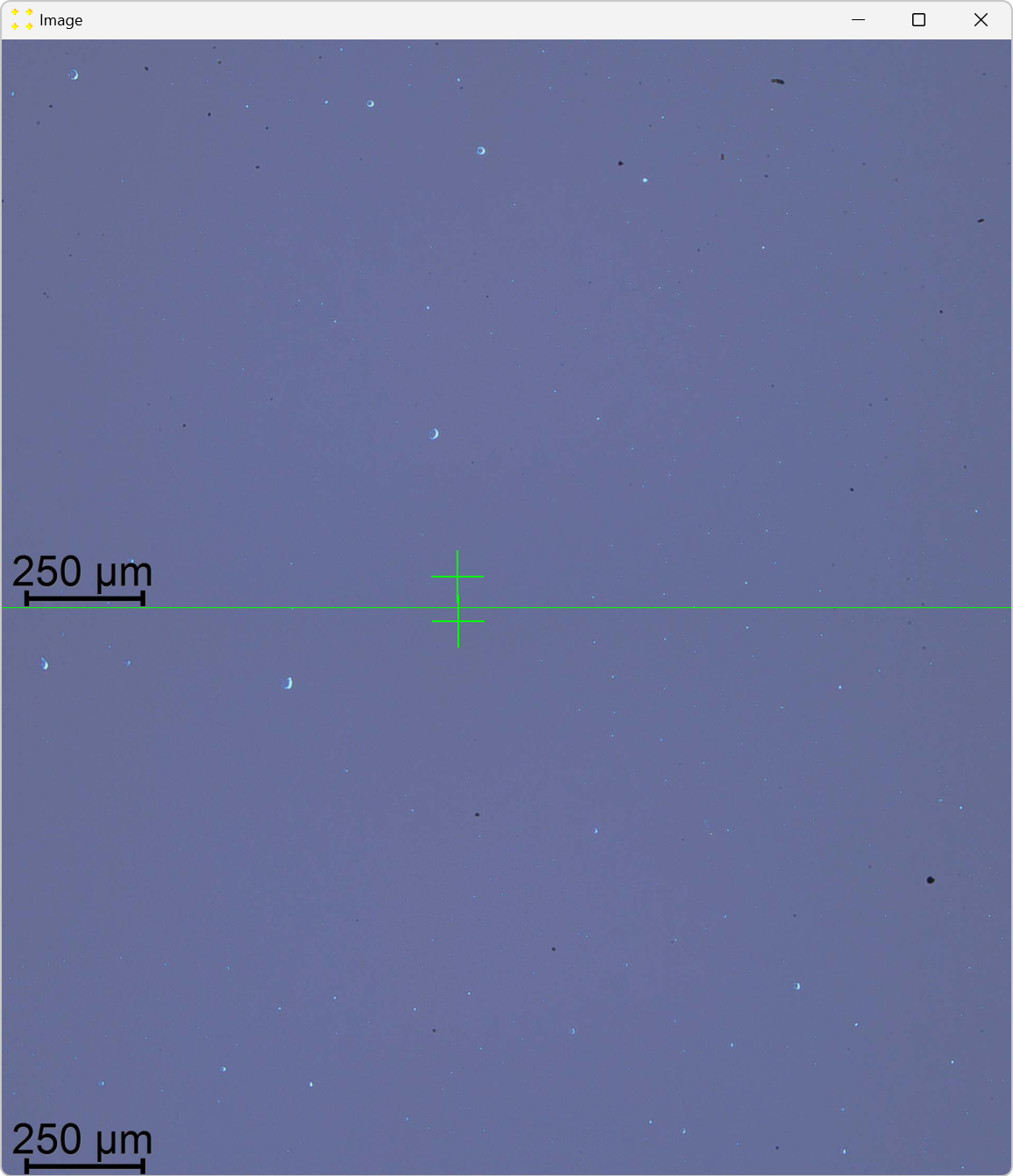
Click the "Calibrate" button in the "Vertical Offset" group box to open the images used to determine the vertical offset between neighboring images. This action will display the images "01.jpg" and "02.jpg" stacked vertically, each with a single mark at its center, as shown in Figure 11. The images are separated by a line of the same color and thickness as the marks. The image "02.jpg" appears below "01.jpg", reflecting the selected settings in the "Stitch" window (based on Figure 2).
Roughly align the marks with the common feature visible in their respective images, as shown in Figure 12.
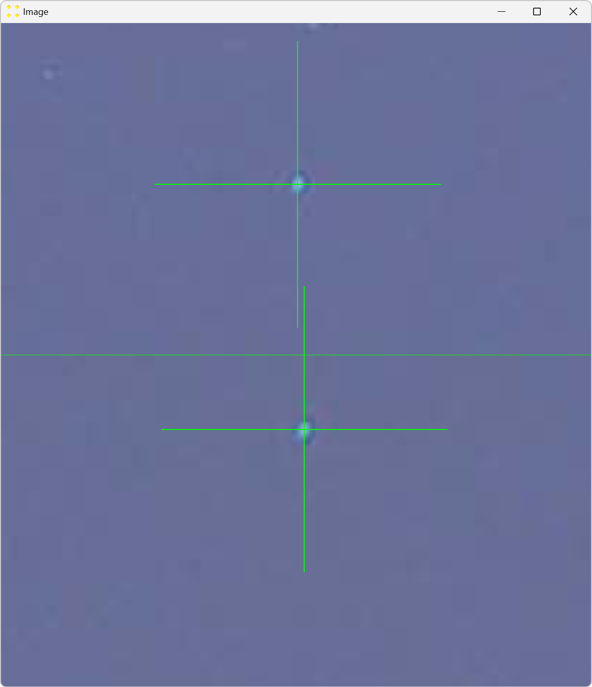
Double-click the marks to zoom in and precisely align them with the common feature, as shown in Figure 13. The zoom-in procedure is explained in detail in Single image.
Close the window with the images and save your changes.
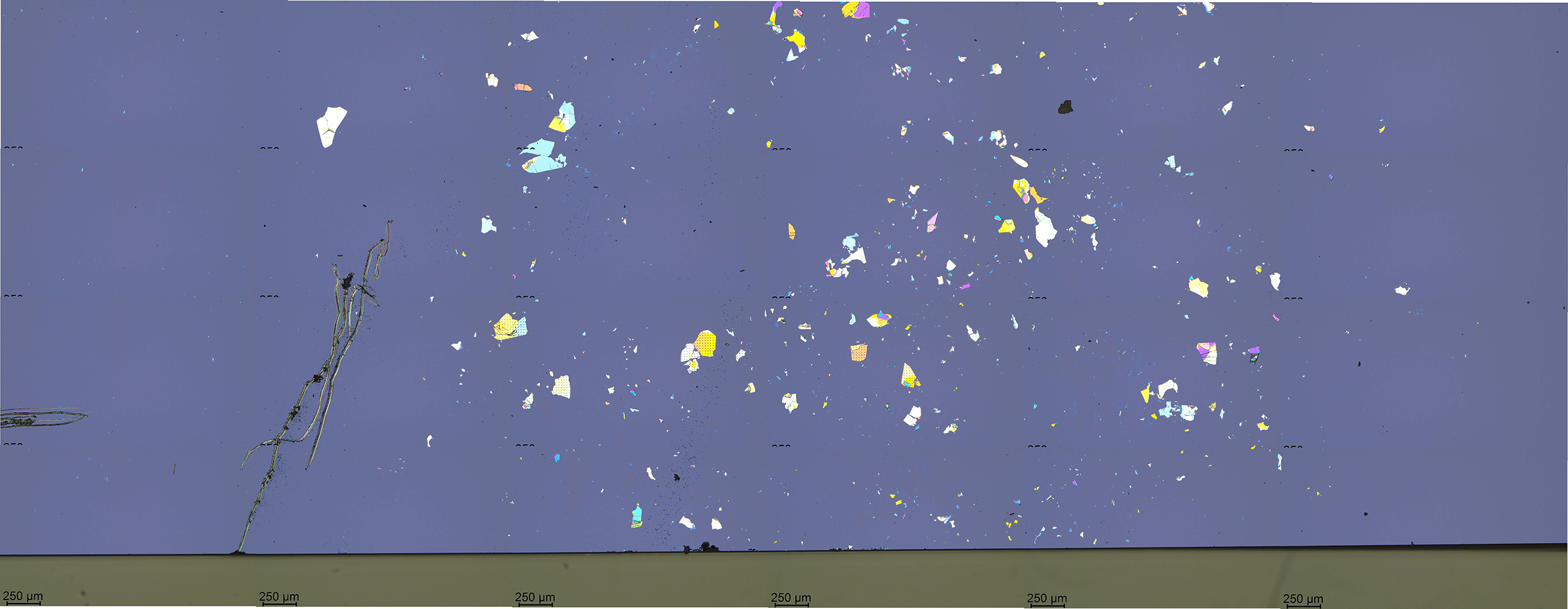
Click the "Stitch" button, shown in Figure 15, to perform stitching. This action will save the stitched mosaic image in the file "01_s01.jpg". The mosaic file is shown in Figure 16. The mosaic image displays a part of a chip with exfoliated hBN.


Notice the offsets "ΔX (X pitch)" and "ΔY (Y pitch)" in the "Horizontal offset" group box (Figure 10). The horizontal offset was calculated based on mark positioning and does not need to be strictly in the horizontal direction, i.e., strictly parallel to the x-axis.
Mathematically, the microscope stage translation vector in the horizontal direction is given in pixels as (1712.253, -3.642). This means the horizontal translation vector is not exactly parallel to the x-axis. However, the magnitude of the y-coordinate of the translation vector is much smaller than that of the x-coordinate, indicating that the horizontal translation vector is almost parallel to the x-axis.
SVGMarks can handle arbitrary translation vectors. For an example, refer to the discussion in Transformed images, where the stage translation vectors form non-negligible angles with respect to the x- and y-axes.
The result of the horizontal calibration was saved in a file with the automatically generated filename "HCal_01_t01_05_t01.svg", as shown in Figure 10. It is recommended to keep the default filename, as this allows the horizontal calibration to be automatically loaded when the "Stitch" window is opened next time. Additionally, if another set of images was taken using the same horizontal stage translation vector, this calibration can be reused by opening the file "HCal_01_t01_05_t01.svg" through the "Open" button (i.e., another calibration is not necessary in this case).

This completes the measurement of the horizontal offset. To determine the vertical offset between images, repeat the same procedure in the vertical direction, as described below.
Notice the offsets "ΔX (X pitch)" and "ΔY (Y pitch)" in the "Vertical offset" group box (Figure 14). The vertical offset was calculated based on mark positioning and does not need to be strictly in the vertical direction, i.e., strictly parallel to the y-axis.
Mathematically, the microscope stage translation vector in the vertical direction is given in pixels as (1.562, 993.125). This means the vertical translation vector is not exactly parallel to the y-axis. However, the magnitude of the x-coordinate of the translation vector is much smaller than that of the y-coordinate, indicating that the vertical translation vector is almost parallel to the y-axis.
SVGMarks can handle arbitrary translation vectors. For an example, refer to the discussion in Transformed images, where the stage translation vectors form non-negligible angles with respect to the x- and y-axes.
The result of the vertical calibration was saved in a file with the automatically generated filename "VCal_02_t01_01_t01.svg", as shown in Figure 14. It is recommended to keep the default filename, as this allows the vertical calibration to be automatically loaded when the "Stitch" window is opened next time. Additionally, if another set of images was taken using the same vertical stage translation vector, this calibration can be reused by opening the file "VCal_02_t01_01_t01.svg" through the "Open" button (i.e., another calibration is not necessary in this case).

Figure 15 displays the "Stitch" window at the end of the calibration.
