SVGMarks can be used to process images for electron-beam lithography or for general purposes.
Use in electron-beam lithography
This part of the manual demonstrates the use of SVGMarks when processing images for electron-beam lithography. You can also watch the corresponding video tutorials. The files used in this manual can be downloaded from the Download section as a single zip file containing the used images and the design file in GDSII format.
After image transformation, the image can be automatically placed in a design file opened in Raith Nanosuite. The image can also be placed in other nanofabrication CAD software by manually inserting the coordinates provided by SVGMarks. If your nanofabrication software is not supported, please contact the author.
Click one of the buttons below to jump to the appropriate section of the manual related to electron-beam lithography.
Single image Stitching SettingsStitching (see also the video tutorial)
SVGMarks can automatically transform multiple images based on the transformation of a given image. This is useful in situations where multiple images are taken by a microscope with a motorized stage, which introduces the same distortion in all the images. SVGMarks can be used to transform all the images at once, based on the previous transformation of one of the images.
This process is called "stitching" because it also allows all the transformed images to be stitched together into a single large image. Such image stitching is also useful when the microscope cannot take the large image at the same (high) resolution as the small images.
The images can be stitched together in two ways:- Transforming each of the small images and then stitching them together into one large image in the design file. This is the approach used by SVGMarks, as described in the example below.
- Stitching the small images together and transforming only the large image. This approach does not require a design file to access the stitched image (i.e., the stitched image can be opened in any image viewer/editor) and will be available in the next version of SVGMarks.
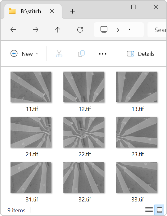
Figure 1 shows the content of a folder containing 9 images taken with a scanning electron microscope (SEM). The images are intentionally rotated about 11 degrees counterclockwise to demonstrate the capabilities of SVGMarks.
To stitch the distorted images together, first, one of the images is transformed using SVGMarks as explained in Processing a single image. Second, the same transformation is applied to all images. Third, the transformed images are stitched together. The whole procedure is explained below.
-
Transform one of the images with SVGMarks as explained in Processing a single image. The choice of the image is arbitrary, but to simplify the stitching procedure, it is recommended to transform the image which is physically located in one of the corners of the structure. In the example shown in Figure 1, the image "11.tif" is selected. Figure 2 shows the result of transforming image "11.tif".
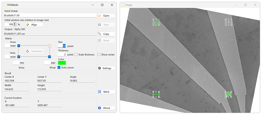
Figure 2. The result of the transformation of the image "11.tif". - Click the "Stitch" button to open the "Stitch" window shown in Figure 3.
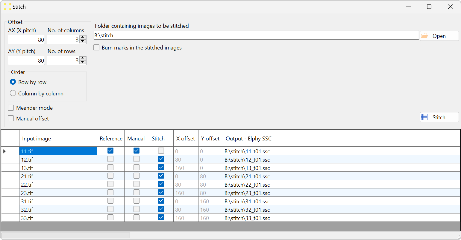
Figure 3. The "Stitch" window, where you can define the images to be transformed and the corresponding stitching parameters. - the image transformed in the previous step ("11.tif") is the reference image with respect to which all other images should be transformed;
- all images to be transformed are located in the same folder as the reference image.
- The "Input image" column contains the names of the reference image and the images to be transformed using the same transformation previously applied to the reference image.
- The "Reference" column contains check boxes indicating which image is the reference image. By default, SVGMarks always selects the previously transformed image (in this case "11.rtf") as the reference image. However, users have the option to choose the reference image by checking the corresponding check box in the "Reference" column. The reference image will not be transformed as SVGMarks assumes that the reference image has already been transformed.
- The "Manual" column is a read-only column that indicates the images that have already been transformed by SVGMarks. This is to inform users that the images, whose check boxes are checked, have already been transformed by SVGMarks and that they may not require the automatic transformation by the "Stitch" option.
- The "Stitch" column indicates which images should be transformed. By default, SVGMarks selects all images apart from the reference image to be transformed. Users have the option to exclude some of the images from the transformation by unchecking their check boxes.
- The columns "X offset" and "Y offset" contain image offsets along the x and y axes, respectively. SVGMarks will not only transform the images selected in the column "Stitch", but also translate them by the corresponding "X offset" and "Y offset" along the x and y axes, respectively. These offsets are calculated with respect to the reference image (hence zero offsets of the reference image) based on the entries in the group "Offset", as discussed further below. However, if the check box "Manual" is checked, the values in these two columns can be edited manually.
- The column "Output - Elphy SSC" contains the full file names of the SSC files that will be generated by transforming the images.
-
The group "Offset", shown in Figure 3 and Figure 4, is used to automatically calculate the offset of the images to be transformed with respect to the reference image. In the case the stitching is not important, i.e, when the images should only be transformed without any translation, the group "Offset" can be disregarded.
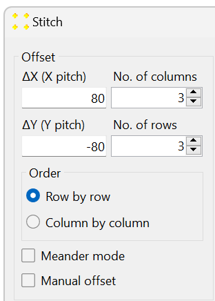
Figure 4. The "Offset" group contains settings that are used to translate the images with respect to the reference image. -
To perform both transformation and stitching (translation) of the selected images, click the "Stitch" button. In this example, SVGMarks will generate bitmap (BMP), SVG, and SSC images for each of the images in the folder (apart from the reference image 11.tif) as if they were manually transformed. The image content of the folder is shown in Figure 6. The first nine images displayed in the figure are transformed bitmap images.
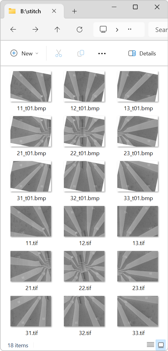
Figure 6. Part of the folder content after stitching. Only images are shown. -
Open the design file in Raith Nanosuite. To open the transformed images, click on "File" → "Open image..." and choose one of the images, e.g., 11.rtf. Repeat until all images are open.
To show the transformed images in the design file, click on the design file window to bring it to the foreground, and then click "Options" → "Show Video. The transformed images will appear in the design file, as shown in Figure 7.
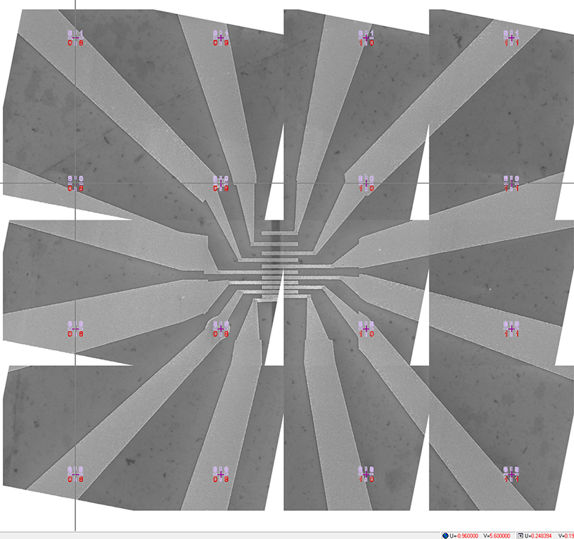
Figure 7. The stitched transformed SEM images in the design file. The white triangles within the image are a consequence of a significant (deliberate) rotation of the individual images. It is recommended that the images be taken with the smallest possible rotation.
By default, SVGMarks assumes that:
In the table at the bottom of the window, SVGMarks lists all images found in the folder of the reference image. If the images to be transformed are located in a different folder, click the "Open" button to browse for one of the images you want to transform. Once the image is selected, its folder will be used.
The table has the following columns:
The images are listed in alphabetical order in the table. The radio buttons in the subgroup "Order" are used to select the order in which they are placed in the actual structure. This is demonstrated by Figure 5. The first three images in the table (11.rtf, 12.rtf, and 13.rtf) form the top row of the structure. The next three images (21.rtf, 22.rtf, and 23.rtf) form the middle row of the structure. The final three images (31.rtf, 32.rtf, and 33.rtf) form the bottom row of the structure. The images are therefore ordered in a row-by-row format in the table, which means that users should check the "Row by row" check box.
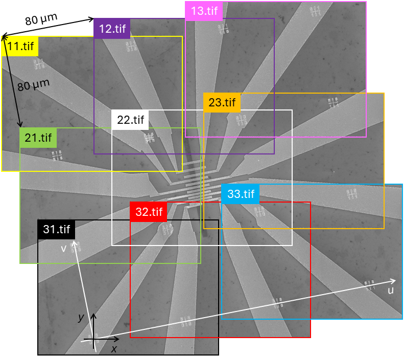
Given that the reference image is located in the top left corner, the offsets along the x and y axes are 80 µm and -80 µm, respectively. Consequently, "ΔX (X pitch)" and "ΔY (Y pitch)" should be set to 80 and -80 in Figure 4, respectively. Finally, the images are arranged in a 3 by 3 matrix. Therefore, both the "No. of columns" and "No. of rows" should be set to 3 in the group "Offset" shown in Figure 4.
The "Meander" check box should be selected if the images are ordered in a meander fashion in the table, which is not the case here. In that case, the meander order would be 11.tif, 12.tif, 13.tif, 23.tif, 22.tif, 21.tif, 31.tif, 32.tif, and 33.tif.